Layout
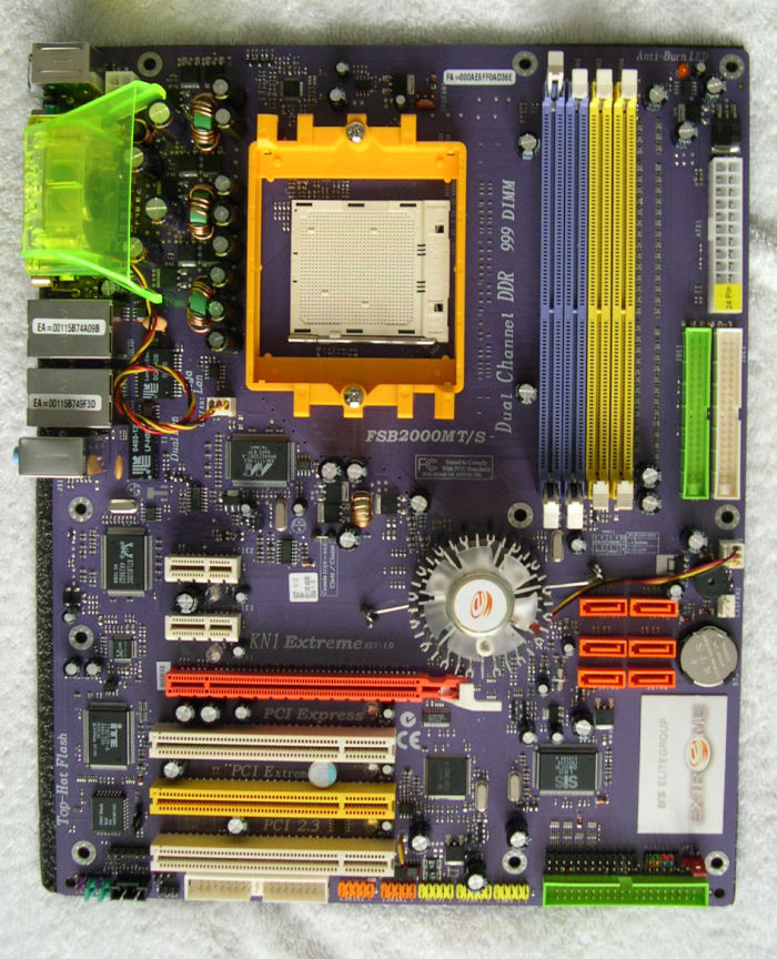
Broadly speaking, the KN1 Extreme isn't a million miles away from NVIDIAs reference nForce4 design, but there are some slight differences. Regardless, let's take a look at the board layout, starting in the top left-hand corner where we find the four-pin ATX12V connector neatly tucked away next to the funnel for the fan situated on the backplane of the motherboard. We then find all of the CPUs power regulation circuitry before coming across the CPU socket itself. You'll then find the four colour-coded DIMM slots where you would expect them to be, and then the 24-pin ATX connector and two IDE channels on the right hand side of the board.
Underneath this, towards the middle of the board, we find the KN1 Extreme's six Serial ATA ports - The bottom two ports are situated quite close to the PCI Express 16x slot, but not close enough to cause any issues when using a long video card. To the left of these ports we find the nForce4's north bridge, covered by a hefty silver heatsink and fan. Moving further across, we find two 1x PCI Express slots above the PCI-E 16x slot, as per the reference design, which allows for a shorter path from the 16x slot to the controller and thus improves signal quality. Along the left-hand edge of the board we find two Realtek chips, controlling both the RTL8100C LAN functionality and ALC655 audio device.
Underneath the 16x PCI-E slot are the boards three convential PCI slots, and under that is the floppy connector. Moving along the bottom of the board gives us two and three headers for added Firewire and USB ports respectively. Finally, we reach the final IDE port available on the board (controlled by the SiS 180 chip above it), a header for the addition of an LPT port, as well as connectors for the usual set of power switches, LEDs and so on.
Speaking of LEDs, the KN1 Extreme is packed with the things, to the point where you may not want to use this board on the Heathrow flight path for fear of aircraft landing on your house. At the top left of the board is an Anti-Burn LED, there to warn if RAM modules have been inserted incorrectly before they burn out or do any other damage. There is also a blue LED on the motherboard for every PCI and PCI Express slot, to indicate whether it is populated and functional or not - If the LED stays on, then a board is inserted and running in the slot, if it flashes then it's empty or not functioning. It could make for a handy troubleshooting device I suppose, but is also quite a potential distraction.
Overall, this is probably one of the better motherboard layouts I've seen in my time, I really can't think of anything to gripe about with it at all.
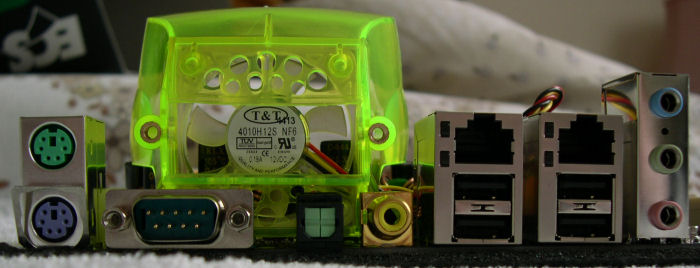
Moving on to the backplane, we find the usual set of PS/2 ports and serial port, before moving on to the optical and SPDIF outputs from the Realtek audio device. Above this we find a fan outlet, designed to draw heat away from the CPU and surrounding area. The rest of the backplane provides us with two RJ-45 ports, four USB 2.0 ports and three audio sockets for line-in, line-out and microphone.