|
 D845PEBT2 in the silicon
Starting at the top left of the board and working our way across and down as usual, we can see how Intel have laid out the board.
The first thing we come across is a fan header and the vertical row of 9 capacitors regulating power to the CPU socket, flanking the socket area itself. Being an Intel P4 solution, the socket area is well defined and the usual black heatsink retention bracket comes supplied even though it's not present in the picture due to my personal heatsink preference not requiring the retention bracket.
Another fan header near the top right corner of the socket area and we come across the pair of DDR DIMM slots that provide the memory support for the board, a total of 2GB.
Finally in the top half of the board and in my favourite position for these components we find the main ATX power header and the IDE and floppy connectors, all oriented vertically. For this reviewer, the top right of the board and oriented vertically is the ideal position for the components when being fit into a decent sized ATX tower case, minimising cable clutter across the rest of the board allowing you to tidy up your layout.
Before we hit the bottom half of the board we have the i845PE chipset heatsink, a stylish silver, fanless affair, helping to keep board noise to a minimum which is a definite plus point.
From the AGP port downwards, everything is in a well sited spot on the board, especially the peripheral headers for things like FireWire, USB2.0 and the Serial ATA connectors which are low enough to be drawn underneath the last PCI slot (ignoring the CNR) if you need to route to the back of your case or in the case of the Serial ATA port, are on the right hand side of the board for good position beside any drive enclosure in a regular ATX case.
There's a final fan header in line with the 4th PCI slot for connecting a case fan if needed.
Finally, in a departure from the last Intel board I used before the BT2, their i850E board supplied with the 3.06Ghz Pentium 4 we had for review, the board has a front case header layout table to let you hook up your power and reset switches and LED's without the aid of a manual. The i850E board was a pain to setup since the board, like this BT2, was supplied without a manual. The BT2 however has the handy layout for the header to let you get going with no fuss.
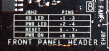 All boards should have something like this!
So all in all, an excellent layout, one I can't find any fault with in terms of my own personal preference. I can nearly grumble about the placement of the auxiliary ATX header near the bottom left of the socket area. But I'm so used to its placement there on P4 boards that I have especially routed that connector from my PSU to be out of the way and still accessible on that part of a motherboard so it's not a problem. Many little layout issues like this will be personal preference.
As far as the ports on the board go, it's worth taking a proper look since it's a non standard layout due to the provided features.
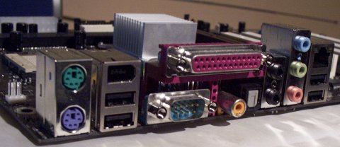 BT2 port layout
You lose a serial port but you gain digital audio capabilities in terms of Toslink and coax outputs from the AD1980 codec which is a fair tradeoff. It appears the CNR slot is usable for digital audio output using a different version of the codec, but that's not implemented on the BT2 and you lose a serial port instead.
|