Layout
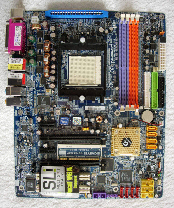
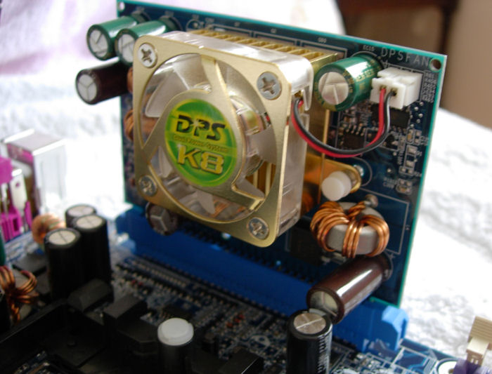
Despite the GA-K8NXP-SLI being packed with features, the layout is still a tidy, well-thought out one, so lets check it out. Starting out, as always, at the top left corner, the first thing we see is the four pin ATX12V connector. To the left of this is a slot for Gigabyte's DPS, or Dual Power System - A six-phase power circuit add-on card designed to provide solid, stable power to the system at all times, while also acting as some additional cooling for the CPU in the process.
Under the DPS slot comes the CPU power circuitry and Socket 939 CPU socket itself, with the CPU fan header located at the bottom left corner of this. To the left of the CPU socket we find the boards four, colour-coded, DIMM slots, and beyond that are both the 24-pin ATX connector along with the ATA and floppy channels. Moving down the board a little takes us to the four Serial ATA ports powered by the CK8-04 SLI north bridge, which can be found covered by a heatsink and fan to the left of the ports. Continuing across, we see the two BIOS chips which comprise Gigabyte's Dual BIOS technology, as well as one of the two chips to provide Gigabit Ethernet to the board.
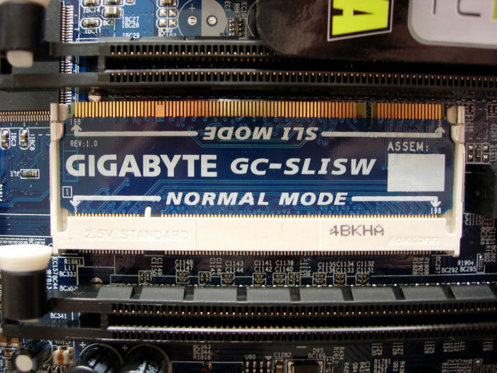
Underneath this arrangement, we come to the GA-K8NXP-SLIs PCI-Express slots, with a PCI-E 1x slot followed by the first PCI-E 16x slot, before that arrangement is repeated again. As with all nForce4 SLI motherboards, a continuity connector is required to physically tell the board whether to operate in its SLI or normal mode. Switching between one and the other simply involves unclipping the connector, and switching it to the desired mode as marked on the small PCB.
To the left of the PCI Express slots you can find chips controlling both the Marvell Gigabit Ethernet adapter and Realtek audio. Underneath the PCI-E slots are the two conventional PCI slots. Finishing off along the bottom of the board, we find headers aplenty for Firewire (one) and USB 2.0 (three) connectivity. We also find our final four Serial ATA ports, and the Silicon Image controller which drives them.
Overall, the board design is good for such a feature-packed one, the biggest potential gripe being that a full-length card in the top PCI Express 16x slot blocks off the airflow to and from the north bridge heatsink and fan somewhat, although not enough to cause any issue by the look of it. Such a card also comes close to blocking off some of the Serial ATA ports on the board, but ends up occupying the gap between two ports and thus stays out of the way.
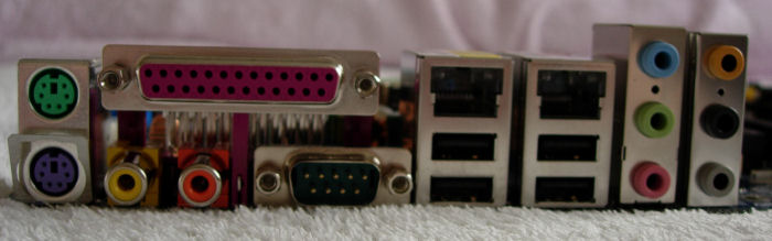
Pretty standard fare on the backplane, where we find PS/2 ports, followed by the coax S/PDIF input and output provided by the Realtek audio controller (The lack of optical output is a shame). Next up is the parallel and serial ports, and to the left of them both four USB 2.0 ports and both RJ45 connections for the two Gigabit Ethernet adapters. Finally, we come to the six sound jacks, four for output, and a line-in and microphone connector.