Layout
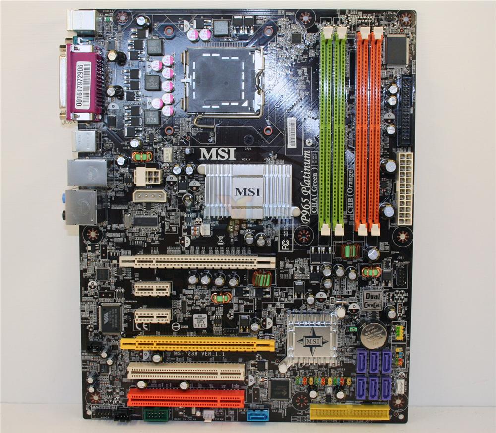
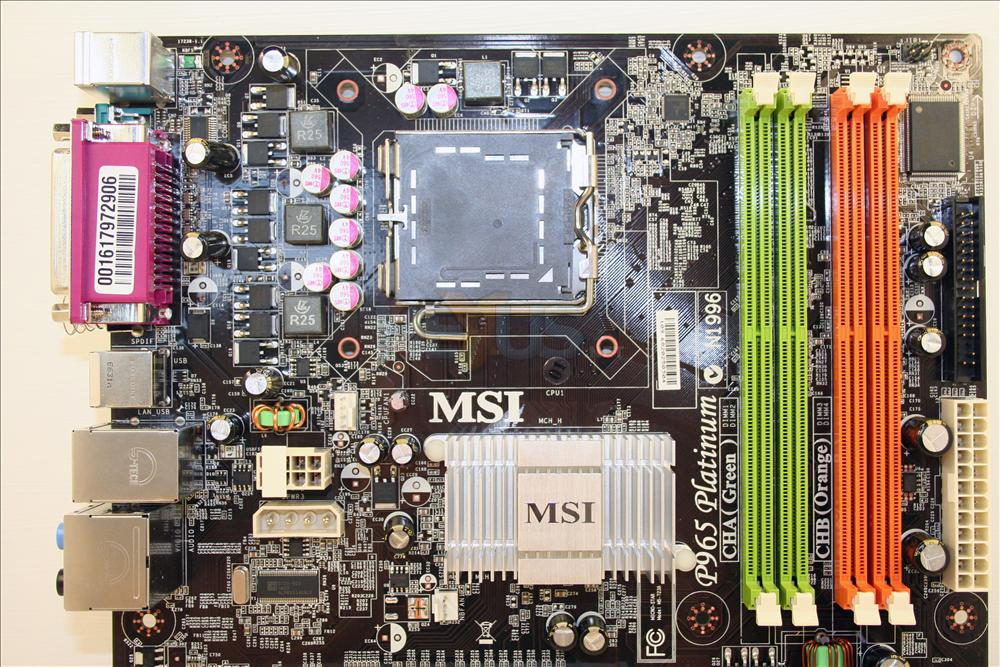
Starting at the top left (as you see it) and working our way down, you see a CPU socket area that's not only free inside the guidelines Intel set out, but also pleasingly clear a little further out from that too. That's not to say all giant LGA775 heatsinks will fit, but it's promising. The first of the board's fan headers isn't far away. 4-pin and specifically for the CPU fan, it's close enough to the fan it'll power so as to be useful. We can't say the same about the 'NB' fan header. Presumably for a northbridge fan, the passively cooled bridge obviously doesn't have one, leaving that 3-pin header as the nearest one to the back of any chassis. For your author at least, though, it was far enough away to make connecting it up impossible.
The memory slots are colour coded and well marked. Each colour denotes a different memory channel, so for dual-channel running you want one stick in a green and one in an orange, or fill the lot up. We used the green slot nearest the CPU, and the corresponding nearest orange one throughout testing.
MSI put the SSI (P4 and P4+ combined) and optional Molex power input connectors next to each other on the south side of the CPU area, to the left of the northbridge 'sink. It's the only part of the board layout we take issue with, much preferring power connector placement to happen on the outer edge of a mainboard to aid cable routing. Unless your P4/SSI cable(s) are pretty damn long, so as to get round the top of the CPU area and down the left side of the board, it'll mean draping the cables across memory and/or northbridge sink at the very least.
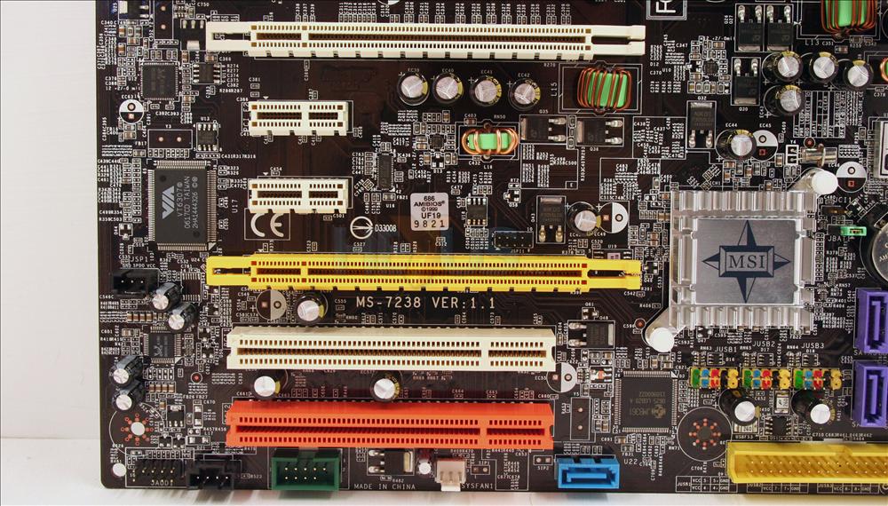
The EATX 24-pin power connector is just past the memory slots on the right, and if you look hard enough you'll spot floppy connector in black just above. The first PCI Express slot is far enough away from the memory slots so that you can change memory config without removing your graphics board. Always cool to see, even if it can mean one less expansion slot. If you run dual-slot graphics in either PEG slot you'll still get a PCIe or PCIc slot free underneath, depending on what slot(s) you occupy.
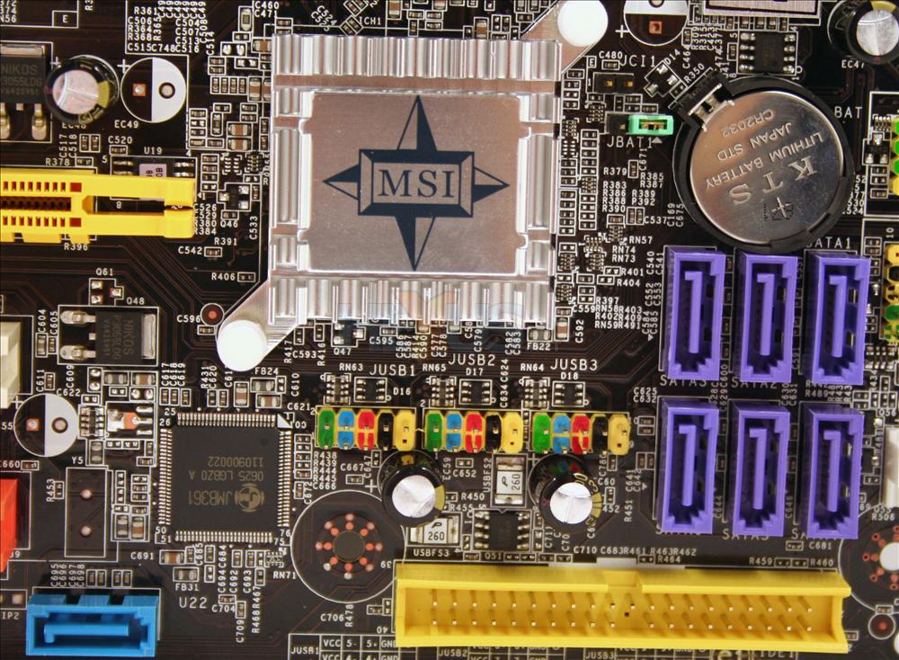
The ICH8R is passively cooled using a low-profile 'sink, with a natty little branding plate held in there for aesthetics. The branding plate rattled noisily when we moved the test PC the board was installed in, although unless you're wiggling your PC about in use for whatever reason, it'll stay put and quiet.
ICH8R means 6 SATA2 ports (the purple ones under the battery), and you can also see the blue SATA2 port near the last PCIc port, which is connected to the JMicron IC mentioned on the page before. The JMicron-attached ATA port is in yellow and right on the bottom edge. Not quite where we ideally like it, but on a board edge at least.
Lastly, we make mention of the front-panel connector pins which are poorly labelled (at least on the tested version of the board), causing us to guess which pins to bridge with the power switch on our test chassis.
Summary
A decent enough layout overall, but the SSI power and ATA connector placements make us sigh a little. Not perfect for us and we're happy to pour scorn and mark it down, but maybe just right for you of course. A mini gallery of other pics follows.Board Images