Layout & Features
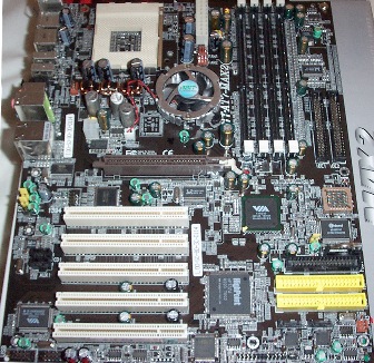
Well ABIT certainly pulled out all the stops when it came to style. This motherboard shows all the qualities of a modder's motherboard, the dark brown/black colour and the shiny, orb like, chipset fan would look great in a case with a window. The board is jam packed with components, there's hardly any blank areas left on the board. Layout wise, the ATX header is ideally placed, IDE connectors are placed on the far right of the board where they should be. I am glad to see ABIT have moved the floppy drive connector up the board a bit, compared to their more commonly recent placing of it at the bottom. Some full tower cases have the floppy drive right at the top, and finding floppy cables long enough can be difficult when the connector is so far away. As usual with ABIT boards you will find the lower ram 'clips' hit long graphics cards such as the Geforce 4 Ti 4600 - this doesn't stop the use of the RAM slots, just makes it a bit fiddly getting them in and out with the card inserted.
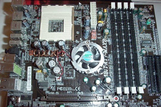
That chipset fan sure does look nice :). The observant of you may notice something not usually found on Socket A motherboards; a P4 auxiliary power connector. With the sheer amount of power AMD processors consume the strain on the 5 volt line is immense. Most power supplies can barely maintain this at 5 volts, and tend to drop to 4.7 volts or lower under load. This can lead to system instability, especially on overclocked and overvolted systems. ABIT have addressed this problem by using a similar power supplement system that Intel Pentium IV platforms have used for some time. By spreading some of the CPU power load to the 12 volt lines the strain is reduced on the 5 volt line and this results in greater system stability. Note that this connector is optional, i.e. if you don't have a power supply that supports the P4 auxiliary power connector then the system will still function.
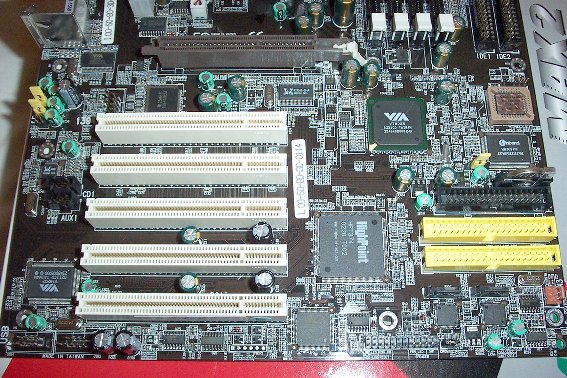
The bottom half of the board shows us the IDE Raid connectors with the relatively tiny serial ATA connectors underneath. The AGP slot now has a retention clip on it that will keep the right end of the card from working its way out (a common problem with some cheaper cases which pull on the card). On the bottom left you have 2 extra USB headers, one of which you can connect to the supplied back plate for another 2 ports. You will also notice that the CMOS reset jumper has a little pull handle on it, making things far less fiddly if you ever have to reset the motherboard.