


ASUS A8N-SLI Deluxe - Layout
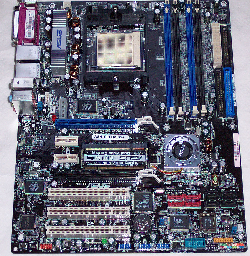
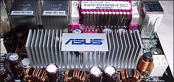
Starting from the top-left corner and working our way across and down, the first thing you come across is three-phase power delivery circuitry for the processor, the MOSFETs topped by a multi-fin aluminium heatsink. Since the MOSFETs do the switching for voltage regulation, they can get very hot depending on what they're feeding. Take a closer look by clicking here.
The CPU socket has plenty of room around it, bar the left edge near the FET cooler. The AMD reference coolers for all current processors fit just fine, however some larger aftermarket coolers will likely foul on it. Something to bear in mind. ATX12V (also called the P4 connector on some PSUs) is nestled in just above the area the cooler occupies. Underneath the socket lies the EZ-Plug, a standard 4-pin Molex connector that helps provide extra power to the PCI Express slots. To the right of that is the 88E111 Marvell chips that provides the physical interface to the on-bridge NVIDIA GigE controller with hardware firewall. To the left of it is a 3-pin fan header.
To the right of the CPU socket area there's a quartet of DIMM slots for you to provide with memory sticks, and a 3-pin fan header sits near those, on the very top edge of the board. 24-pin EATX power is next, with a floppy cable connector just infront of it on the board's right edge. The pair of PATA ports round off that grouping of board features.
The topmost PEG16X slot for your graphics card (even if you run just one, it's where you'll put it) marks the top-bottom board split. There's enough clearance between it and the DRAM slots to allow you to change memory even with a large graphics card installed.
Two PCI Express 1X slots separate it and the second PEG16X slot. The continuity connector that remaps the lane bundles to the slots is nearby. It initially comes configured (at least the review sample did) in single-GPU mode. It's like a miniPC or SODIMM connector and you just turn the card around to activate SLI mode (an 8X + 8X lane remap), with the power to your PC off of course. To the left of the 1X slots lies the tiny ALC850 CODEC.
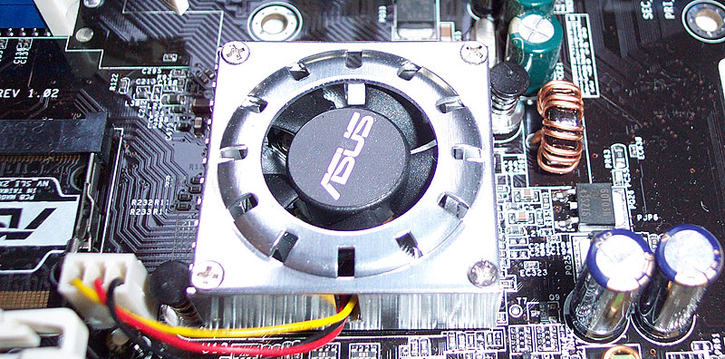
The cooler for the nForce4 chip is horrible. The heatsink part of the assembly is aluminium and it wraps the 8000rpm fan inside a shroud that seems to only serve to make it louder. Permit me a whinge. If you're going to spend large sums of money engineering so many features onto a mainboard, along with all the testing required to make sure the integration is done properly and it's a high quality product, as you'd expect from ASUS's Deluxe range of boards, don't fit a fan that'll drive the user of all that power and all those features mad.
The Marvell 88E8001 GigE controller that rides the PCI bus (why not choose a PCI Express version and put it on one of the spare lanes?) sits to the left of the PCI Conventional slots, along with the PCI Conventional-attached Texas Instruments FireWire400 controller. The Sil3114 is tucked up next to the slots on the right-hand side. Just along from that are the four SATA ports that hang from the Sil3114, coloured red. I'd prefer if they weren't behind the four black ports that are connected to the nForce4 bridge, in terms of routing cables to and from them and the drives in your chassis, and I'd also prefer if they were oriented 90° clockwise.
The temperature monitoring chip is below the Sil3114 ports, out of the way, and the front-panel case connectors, headers for extra USB2.0 and FireWire400 ports, and the serial port connector, are all on the bottom edge of the board. Finally, the last 3-pin fan header is nearby in the bottom right hand corner of the board.
Overall
In this reviewer's opinion, it's a solid layout that does nearly everything right in terms of placement. The only issue is the location of the EZ-Plug connector and the fan header nearby, causing you to run a PSU cable loop between CPU and topmost PEG slot (which might make the rest of the connectors on that cable loop useless). Everything else is sensibly placed with power connectors on the edge of the board, PATA and SATA there too and the pin headers for extra ports are on the bottom edge of the board, out of the way.The main issue with the board, which isn't really a layout defect as such, is the horrible bridge fan for the nForce4. At least it's in between the major areas for graphics cards, meaning there's scope for swapping it for something larger, but passively cooled.


